
DIY Kit for 10-48 inch LED LCD TV Backlight Driver Board 11-30V Input
ILMAINEN toimitus
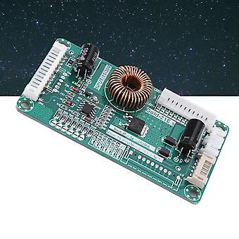
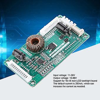
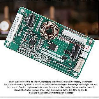
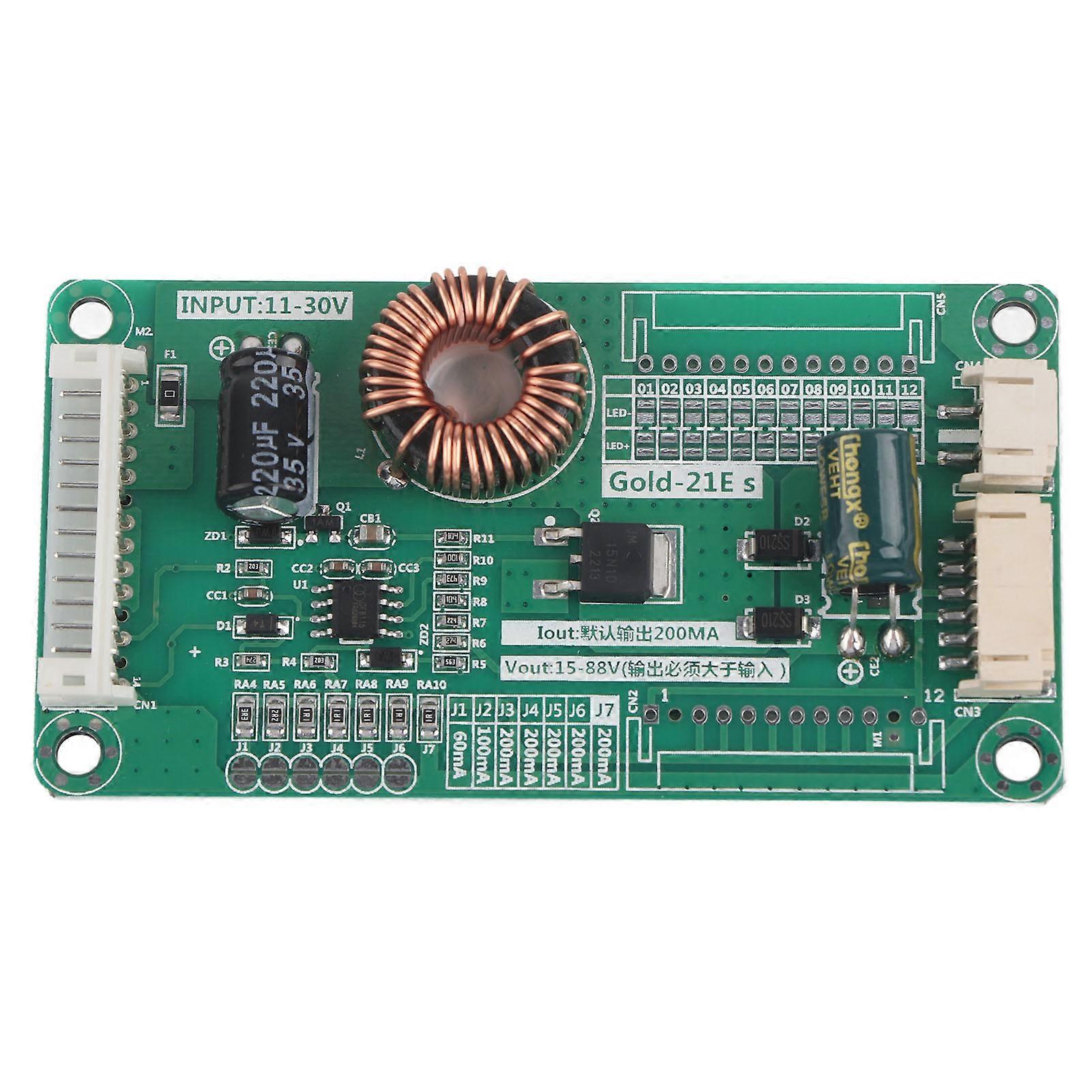
DIY Kit for 10-48 inch LED LCD TV Backlight Driver Board 11-30V Input
- Merkki: Unbranded
DIY Kit for 10-48 inch LED LCD TV Backlight Driver Board 11-30V Input
- Merkki: Unbranded
| Ohjevähittäishinta: | |
| Hinta: | |
| Säästät: | 4,00 € (25%) |
Varastossa
Hyväksymme seuraavat maksutavat
Kuvaus
- Merkki: Unbranded
- Kategoria: Televisiot
- Fruugo ID: 415721723-877512623
- EAN: 7908770068271
Tuoteturvallisuustiedot
Katso tätä tuotetta koskevat tuoteturvallisuustiedot alla
Seuraavat tiedot tarjoaa tätä tuotetta myyvä riippumaton kolmas osapuoli.
Tuoteturvallisuustarrat

Toimitus ja palautukset
Lähetetään 2 päivän kuluessa
-
STANDARD: ILMAINEN - Toimitus välillä ti 28 lokakuuta 2025–ti 04 marraskuuta 2025 - ILMAINEN
Lähetyspaikka: Kiina.
Teemme parhaamme varmistaaksemme, että kaikki tilaamasi tuotteet toimitetaan sinulle toiveidesi mukaisesti. Jos sinulle toimitettu tilaus kuitenkin on puutteellinen tai sisältää tilaamattomia tuotteita, tai jos et jostain muusta syystä ole tyytyväinen tilaukseesi, voit palauttaa tilauksen kokonaan tai osittain. Saat tuotteista täyden hyvityksen. Näytä koko palautuskäytäntö
Tuotteen vaatimustenmukaisuustiedot
Katso tätä tuotetta koskevat yhteensopivuustiedot alla.
Seuraavat tiedot tarjoaa tätä tuotetta myyvä riippumaton kolmas osapuoli.
Valmistaja:
Alla oleva informaatio sisältää Fruugossa myytävän tuotteen valmistajan yhteystiedot.
- Wuhan Jinxingkai Network Technology Co., Ltd.
- Wuhan Jinxingkai Network Technology Co., Ltd.
- No. 1-1, Door 57
- Shihua Village
- Qingshan District
- Wuhan
- CN
- 430000
- goldxinks@163.com
- 0086 17786498762
- https://shop01473o1711614.1688.com/page/creditdetail.htm?spm=a261y.7663282.shopNavigation.1.6310755czE9SFQ
Vastuuhenkilö EU:ssa:
Alla oleva informaatio sisältää EU:n alueen vastuuhenkilön yhteystiedot. Vastuuhenkilö on EU:n alueella sijaitseva nimetty talouden toimija, joka on vastuussa asianomaisen EU:n alueelle myytävän tuotteen vaatimustenmukaisuudesta.
- None
- Kequ Technology s.r.o.
- Pražákova 1008/69
- Štýřice
- Jihomoravský kraj
- Brno
- CZ
- 63900
- christopher25106@outlook.com
- 420608214795